Select a topic from the list below.
Hardware (drives/headstages/etc)
1. How can I tell what the version of my Axona system is?
2. Are your drives suitable for use in mice/rat pups?
3. Do you make microdrives with Omnetics connectors?
4. What kind of connectors do you use on your drives?
5. What kind of connector is I/O socket on dacqUSB?
6. What kind of connectors do you use on your cables?
7. Should the ground (GND) pin on the Axona headstage be connected to a ground electrode?
8. What is the maximum tether length I can order?
9. How do I obtain the signal from an analogue channel of the Axona system?
10. How do I connect my external stimulus isolator to dacqUSB?
11. I'm having remote control problems, what should I do?
1. What Windows operating system can I run the Axona software on?
2. I'm getting a "DacqUSB.dll is missing from your computer" error
3. Are the dacqUSB and TINT programs open source?
4. Is there currently a way to observe the cluster space/cluster cut in real time while recording?
5. In TINT, how can I plot the firing maps modulated by speed?
6. TINT message log displays "x position 832 = 315! (x_max = 313)", what does this mean?
7. When cluster cutting in TINT, what do the spike analysis parameters next to the waveform window mean?
8. What is the maximum limit for different features in TINT?
9. What type of files and file extensions the Watermaze analysis supports?
10. What file formats do TINT and fRate support?
11. In the polar plot window in TINT, what is the yellow circle?
12. How does TINT determine the phase of theta?
13. How do I view my raw recording data in TINT?
14. DacqTrack crashes as soon as I open it; what is happening?
1. The headstage is working, but there is no signal in dacqUSB
2. Channels 1-16 work fine with a simulated signal, but the signal looks wrong/doesn’t appear with channels 17-32
3. Some of my channels are excessively noisy without any real signal, what can I do?
4. Can I record units and EEG from the same channel/electrode?
5. For long recordings, how can I to split the output into different file sizes during acquisition?
6. I have an Axona system and stimulus isolator, can I use these to simultaneously stimulate and record from one area using the same electrode?
7. I'm having problems with saturation during recording, what should I do?
Raw Recording:
8. What is the structure of he single units format, and how does it differ from raw?
9. How can I convert my raw data files to a more usable format?
10. Immediately after the recording the program displays "warning-10 packets lost" error; what does this mean?
11. During recording, the live oscilloscope traces seem to not be there, how can I view this?
Transistor-Transistor Logic (TTL) Input Signal
For more basic info about TTL, click here
Connecting to the Axona system:
1. Does the camera use both inputs and outputs? How many? How many TTL inputs are free to use?
2. Do I have to use input 16 (pin 44) for the camera? What does it mean when it says it is “internally set�
Using the software:
3. Does the software require TTL to always be ON, and OFF only when there’s an event? Or the other way around?
4. Can I visualise the TTL signal somewhere on the oscilloscope/record it on a separate channel?
5. Is there a control script that saves my data based on a TTL signal?
6. How can I send the TTL outputs from infrared sensor crossings (or other outputs) to dacqUSB to create timestamps?
How can I tell what the version of my Axona system is?
If you are unsure about the number of channels your system has, or what kind of referencing your system has, please consult the Axona Preamp Type Guide (must be logged in).
Back to Top
Are your drives suitable for use in mice/rat pups?
We sell many different kinds of microdrives, some that are lighter and smaller to work better with mice, but typically are capable of recording fewer channels because of this. Our most commonly ordered versions are the 8 or 16 channel (2 or 4 tetrode) reusable drives, but we do custom disposable drives up to 64 channels. Please see the products web page for information about the weights of each of these drives.
Back to Top
Do you make microdrives with Omnetics connectors?
We do not currently offer ready-made Omnetics compatible drives, although there are two options available to you:
1) Buy bare steel ‘poor lady’ frames and individual Omnetics connectors from us, wire the electrodes directly to the connectors, and cement them onto the poor lady frames. The frames are thus reusable, but the Omnetics connectors are not. We do sell headstages with Omnetics connectors that are compatible with our cables and system.
2) Purchase 16 or 32-channel MillMax connector drives from us along with an Omnetics-MillMax adapter. The pin-out and spacing of the Omnetics connectors is actually specifically designed to mate with a 32-channel TBSI wireless headstage if you intend you use one of those. Please note the adapter will add a small amount of weight during recording.
Back to Top
What kind of connectors do you use on your drives?
Our reusable drives come with easy-plugging Axona connectors (8-16 channels), or MillMax connectors (16-32 channels). All our disposable drives have MillMax connectors. They come from Digikey, and are part numbers ED85100-ND, with mating part (on the cable and animal) being ED83100-ND. Pin spacing is 0.05" in x and y.
Back to Top
What kind of connector is I/O socket on dacqUSB?
The socket is a 44-pin high density D connector. To make it easier, the plug that goes into is available from Farnell (part #: HDB44PTD)
Back to Top
What kind of connectors do you use on your cables?
All our cables have a 25-way socket D-connector that plugs into our pre-amp and our standard male MillMax connector (see above) at the other end to plug into the headstage. The D-connectors come from Farnell (part number: 113-2412).
Back to Top
Should the ground (GND) pin on the Axona headstage be connected to a ground electrode? How does this pin effect the daqUSB system?
Ground goes to a skull screw via your implant. It's critical in single-ended recording, otherwise the electrode voltages don't have a baseline and daqUSB will have trouble reading your signal properly/be overwhelmed by noise.
Back to Top
What is the maximum tether length I can order?
Our standard cable length is 3m, which we sometimes increase to 4m, and only very rarely for a very small number of labs do we extend this to 5m. There are a couple of reasons for this. The first is the robustness of the fine wires in the cable –we need 2x the cable length uninterrupted when making the cables, and the wires arrive from the supplier with frequent breaks, so it would be extremely unlikely that we would be able to get 14m uninterrupted pieces for each of the individual strands (14m is necessary for a 7m cable). The second reason is that longer cables mean an increased driving load for the headstage, and thus increased noise.
If you absolutely need 7m cables, then we could do this by splicing together multiple pieces. But a better solution would be to have the preamp located in such a way that it is closer to the animal. Most labs have a little shelf mounted to the ceiling above the apparatus, where the preamp then sits, to minimise the distance between the animal's furthest movement and the preamp itself. The ribbon cable between the preamp and system unit is 4m long, so that plus a 5m cable would give you a 9m distance between the system and animal in total.
**Note: If you do put the preamp on a shelf, please make sure it doesn't hang next to fluorescent lights on the ceiling or near an air conditioning/ventilation unit as these are both producers of substantial electrical noise.
Back to Top
How do I obtain the signal from an analogue channel of the Axona system? E.g. the amplified signal for detection of a field event while the signal is still being recorded.
At the moment, this is what you need to do:
1) In dacqUSB, go to Tools|Options|Audio and then in "Audio mode" select Continuous.
2) Now, whatever channel is selected as the trigger channel in the oscilloscope will be fed to the left stereo output pin on the 3.5 mm connector OUT1 on the front panel of the system unit.
The signal will have the same settings as it has on the oscilloscope, interms of filtering and gain.
Back to Top
I would like to use an external stimulus isolator (World Precision Instruments Stimulus Isolator (SI) A 365) for LTP studies using the dacqUSB system, but I am having trouble getting the system to trigger current delivery from the SI. I am using the Digital I/O port with a cable that is currently connected to the +5V and GND pins. According to the Axona manual, in addition to those two pins I need to have connected the SI to an external input channel that I specify (page 46 Axona manual Rev 1.2.0). I am not sure how/where to connect the external input channel.
The answer to your question depends on exactly what kind of stimulator and stimulus isolator you use. There are essentially two options: the first is to use the dacqUSB built-in stimulus generator plus an external stimulus isolator, and have the internal stimulator turn the SI on and off (the system is the "master" and the SI is the "slave" in this case); the second option is for "intelligent" SI devices that are capable of generating the stimulus pulses themselves. In this case the dacqUSB system is the "slave", and you need to feed the stimulus output pulse from that device into one of the dacqUSB input channels, so it has a way of knowing when the stimulus has occurred. That's what the paragraph on p46 of the manual is all about.
External stimulus isolators like the WPI 365 that can't generate its own pulses need to be driven by the dacqUSB system. So, you need to do three things:
1) Connect the dacqUSB built-in stimulator output (pin 34 on the DIGITAL I/O port, plus pin 32 for ground) to the WPI "INPUT" connector -- you don't want to be connected to +5 and gnd, otherwise your stimulus current will be always on.
2) In the Stimulator menu in dacqUSB, go to the “Patterns...†menu item and set up the stimulator pattern you want to have
3) In the evoked potentials setup tab, select "Trigger from built-in stimulator" (if you are generating isolated pulses, you'll want to trigger on "Start of pulse", but if you're producing trains of pulses, such as for tetanization, you'll want to trigger on "Start of train" otherwise you'll get trigger events for each pulse within a train).
Configured in this way, you don't need to feed anything back to the system's inputs, because the system is driving the pulses, so it already knows when they happened.
Back to Top
Not all of the clicks are being registered by the system. I have tried to change the battery in the remote and I have tried a different system unit/remote control which has the same issue. What should I do?
First try pressing down on button with fingernail or pen to ensure good contact (recently buttons made stick a bit). Try with a diff system if possible to rule this out. Also, clicking too often can cause issues since it's not designed to register high rates of clicking.
One thing that could be an issue is that the receiver is shielded inside the metal box, and may not be receiving the signal as well as it could (although should be able to receive in a 2-3m range). You can test this hypothesis as follows: on the "DIGITAL I/O PORT" there is one pin which is connected to the antenna input on the receiver. It is pin 44, the bottom-most and left-most pin on the connector. You could try to attach a wire as an antenna to that pin to see if that improves the reception of the signal, and thus the robustness of detection.
The male DIGITAL I/O PORT mating connector is from Farnell part #:107-1810. Click here for the UK specific link.
The manual says that pin 44 is either remote control or channel 16 and it has to be internally set. How do I change this?
The default is for it to be set to remote control, but you can check: take the lid off of the system unit, and look at the top-most board in layer-cake of circuit boards. In the area marked by a blue rectangle in the following diagram, are four jumpers. They should all be aligned, and on the left two of each row of three pins, in other words, the jumpers should be directly next to the text ON CH1 CH2 CH3.
Back to Top
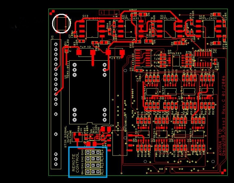
(click to enlarge)
What Windows operating system can I run the Axona software on?
The software works with Windows XP, 7 and 8, both 32-bit and 64-bit. When you get the system, you will see on the installation instructions that there are two different links, one for 32-bit and one for 64-bit, according to which OS type you have.
Back to Top
When I try to install dacqUSB, I get an error message reading: "The program can't start because DacqUSB.dll is missing from your computer. Try reinstalling the program to fix the problem."
1) Check that a previous version of dacqUSB isn't already installed on your computer. If it is, please uninstall that first and try again.
2) Check that you are trying to install dacqUSB from a full setup application and not just a program executable. For the latest full setup files, please log in to this website and visit the Downloads page.
Back to Top
Are the dacqUSB and TINT programs open source?
The dacqUSB and TINT programs aren't open source currently. The license fees for these products allow us to provide support for the software and to improve it.
Back to Top
Is there currently a way to observe the cluster space/cluster cut in real time while recording?
A live clustering display is in development for an upcoming version of dacqUSB, which should be released soon.
Back to Top
In TINT, how can I plot the firing maps modulated by speed?
In the fields window, select “s†for “modulationâ€Â. You need both val 1 and val 2 to set the lower and upper limits. These are both in cm/s, and a spike will be included in the map if the animal's speed was (>= val 1) AND (< val 2).
Back to Top
When loading a file in TINT, the message log will sometimes display something like "x position 832 = 315! (x_max = 313)". What does this mean?
If you define a bounding window in dacqUSB's tracker setup, the coordinates that get stored are relative to that window. If the left boundary (relative to the camera's native coordinate system) is 100, and the right boundary is 400, then the width of the window is 301, and coordinates in the data file should only run from 0 to 300. Somehow this doesn't fully work (a bug in dacqUSB to be fixed), and the odd position point may "spill" out of the window boundaries. Please note that this has no impact on your recording files or results.
Back to Top
When cluster cutting in TINT, what do the spike analysis parameters next to the waveform window mean?
Please see page 13 of the TINT manual for more information. However, we are currently in the process of updating the manual and parameters ‘En’ and ‘Ar’ don’t appear. These stand for "Energy" and "Area". They are parameters some people use for cutting -- the first (also called the L^2 norm) is basically the square root of the sum of the squares of all of the sample values that make up the waveform. See http://mathworld.wolfram.com/L2-Norm.html. The second on (the L^1 norm) is the sum of absolute values of the all of the sample values that make up the waveform ("the area under the curve"). See http://mathworld.wolfram.com/L1-Norm.html. They offer a wave of building shape into the cutting process, in the sense that a fat spike will have a different energy and area compared to a narrow one.
Back to Top
In TINT, what is the maximum limit for different features? So for example, max limit for Amp seems to be set to 200uV, is this right? What do the axes in TINT translate to in terms of real uV values?
The limits for features in TINT are determined by the gain of the channel. The maximum extent of the amplitude/peak/trough, etc. axes is equal to the full scale value you would see for the particular channel in the dacqUSB oscilloscope. Suppose you have a gain of 10000 set for channel 1. If you look at the oscilloscope display for a channel with gain 10000, you will see that the amplitudes displayed on the scope channel range between -150uV and +150uV (the formula is 1.5V/gain, so 1.5V/10000 = 150uV).
This means that the full scale range for this gain is 300 uV. Thus, if you load tetrode 1 into TINT, then the 1A axis in the clustering display will be of size 300 uV. So the amplitude of a dot along the top edge of a cluster window with the 1A axis being the vertical one will be 300 uV (and 0 at the bottom of that window, with a linear mapping in between).
Back to Top
What type of files and file extensions the Watermaze analysis supports?
Our watermaze software primarily supports position files in our standard dacqUSB .pos format, which is a binary format that custom to our tracking systems. There is also a text file which specifies the setup (platform locations, things like that). The file format details are freely available if somebody wanted to write a converter to use our watermaze software with some other position data format. It also supports an ASCII text file mode which is quite straightforward to use, which consists of a first line describing basic trial parameters (tab-separated): rat, trial, date, latency, platform-x, platform-y (for example: 4307, 9, 9 October, 2012, 120.037, -9103, -2381). Then a second line which is simply the number of position points "N", followed by N more lines that each consist simply for x-coord/ y-coord pairs (separated by tabs). The main difference in support between .pos and ASCII modes, is that the user has to enter calibration values, pool dimensions, and things like that manually for ASCII files, whereas the .pos format encodes this information automatically.
Back to Top
What file formats do TINT and fRate support? With Tint once you load the Axona .set file it will incorporate the Axona tetrode, eeg, pos data, but is there a way to use any other file format?
Tint and fRate only support our own data formats, as you say, the tetrode, eeg, pos and inp (digital I/O) files. There are no "generic" file reading capabilities in these programs. Again, the formats are freely available, but they are highly specific to our recording system hardware. Regarding fRate, it's basically an old tool that Jim wrote for the Mosers years ago to analyze spike firing according to various criteria, but has other little things that it does (like PSTHs) which should really be incorporated into Tint eventually. But since most people do their own analyses in Matlab these days, he hasn't been motivated to integrate the fRate functionality.
Back to Top
In the polar plot window in TINT, what is the yellow circle?
The short answer is that the yellow outline shows predicted firing rates given the proportion of time the animal spent looking in each direction.
The long answer is that it is the predicted rate of firing as a function of direction according to the distributive hypothesis method of Muller et al. (Muller, R. U., Bostock, E., Taube, J. S., Kubie, J. L. On the directional firing properties of hippocampal place cells. J. Neurosci. 14: 7235-7251, 1994). The specific calculation is given in Cacucci et al., (Cacucci, F., Lever, C., Wills, T. J., Burgess, N., O'Keefe, J. Theta-Modulated Place-by-Direction Cells in the Hippocampal Formation in the Rat. J. Neurosci. 24: 8265-8277, 2004). If you look in the "Distributive Hypothesis and MLM Analyses" section (http://www.jneurosci.org/cgi/content/full/24/38/8265), the yellow line shows the result of the calculation of RPred(theta), the first equation in that section.
Back to Top
How does TINT determine the phase of theta?
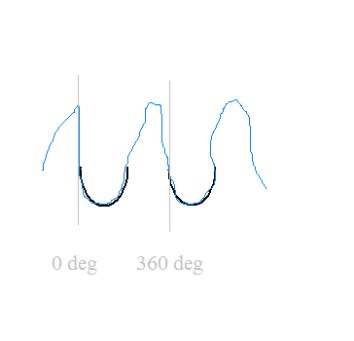
The phase of theta in Tint is determined crudely by fitting half-sinewaves (just the trough part, shown in black in my rather rough drawing, attached) to the ongoing waveform (shown in blue). When a good fit is found, the zero-crossing at the beginning of the cycle is called 0 degrees. The beginning of the next fitted wave is 360 degrees for the last cycle, and 0 degrees for the next cycle. These zero-degree points can be seen in the Tint time window (and my drawing) marked by the grey vertical lines, and the fitted half sinewaves are also shown in Tint. If the theta wave were perfectly sine-shaped, the trough would therefore be at 90 degrees, and the peak at 270 degrees.
The two parameters are actually in "pixels", and work as follows: the quality of the fit is taken as mean squared distance (msd) of points in the waveform from points in the half-sinewave. The theta fit threshold is the worst value for the msd that will be accepted as a valid fit. For the second parameter, theta min U sep is the closest together two cycles are allowed to be, in pixels. With the display interval set to 3000 ms, then one pixel is 4 ms, so with the default value of 12, it means that after a fit has been made, the next fit won't be attempted until 48 ms further along in the data. The algorithm cycles through a range of possible half-sinewave widths trying to find a fit that is better than the theta fit threshold. The range is currently fixed to 6 Hz to 15 Hz.
Back to Top
How do I view my raw recording data in TINT?
You need to convert to single units before you can load the data into Tint. To do this: in dacqUSB, under the File menu, is an option called "Convert data file format" that does it. Click on it, browse to the data you want to convert, and click on Open. This opens a second file dialog with the caption "Save recorded data as...". At this point, you go to the "Save as type:" drop-down at the bottom, and to produce Tint-compatible data, select "Tint files (*.set)". There are also options to save in other formats, like Plexon.
Back to Top
DacqTrack crashes as soon as I open it; what is happening?
1) Check what operating system you are using; currently dacqTrack does not support Windows Vista. It is recommended that you upgrade to a newer operating system, or revert to Windows XP.
2) Uninstall dacqTrack, download the latest version from the Support section of our website, and reinstall. If you are still experiencing problems after rebooting your system, please Contact Us.
Back to Top
During recording there is no signal at all despite the headstage LEDs working fine. Simulated signals but also failed to be picked up in dacqUSB. What’s happening?
1) Check that your preamp has the correct amount of modules for the channels you are trying to record (see preamp types guide)
2) Try closing dacqUSB, turning off your pre-amp and system unit, and restarting the system. If this doesn’t work, turn off the system again and delete the last.set file to try to reset to default settings before turning it on again.
Back to Top
Channels 1-16 work fine with a simulated signal, but the signal looks wrong/doesn’t appear with the same headstage/cable plugged into channels 17-32. What’s going on?
1) Check that your preamp has the correct amount of modules for the channels you are trying to record (see preamp types guide)
2) Check what you have your references and channel filters set properly for your system type. Often the problem is that the references are all chosen from channels 1-16, for all of channels 1-32 when the system is not 'free-referencing'. Hence, when the headstage is plugged into 17-32 and nothing is plugged into 1-16, having your channel filter set as signal-reference (sig-ref) gives bad results.
Back to Top
Some of my channels are excessively noisy without any real signal, what can I do?
1) Check that your system is physically grounded. If you are using an arena for your animals, it may be necessary to connect a spare ground pin on the system to the arena.
2) Check your references settings; if you have your channel set to a particularly noisy reference, it will affect the signal.
3) Check the Axona system version. If you have a free-referencing preamp: open DacqUSB abd select Tools -> Options.. from the top menu. In the dialogue that opens, select the 'Preamp type' tab and make sure 'Unlimited referencing' is selected. If you have an 8-reference system, select that option (sometimes 'Auto-detect' produces an error).
Back to Top
Can I record units and EEG from the same channel/electrode?
With the current base system, you are only able to select a channel to record either units or EEG. However, if you really need to do this and you have a system that is at least 32 channels, you can purchase an input replicator from us. This small bit of hardware connects a 16-channel cable to two preamp inputs and "copies" the 16 channels to the second input. So, if it were plugged into channels 1-16 and 17-32 connectors on the preamp, then electrode input 1 will be fed to both 1 & 17 in the system, etc.
Back to Top
For long recordings, how can I to split the output into different file sizes during acquisition? For example is it possible to set a maximum file size such that as soon as one file reaches a maximum a new one is opened with serial file naming?
It's easy, although you can't do it by file size, but you can do it by time. There's a mechanism that lets you specify that you want to record N trials of X seconds duration each, and the gap between trials is pretty short (a few seconds max, provided the recorded data destination is on the local hard drive and doesn't need to be copied over a network connection). You specify a filename prefix and the program appends incrementing numbers to the end of that prefix for each trial.
If you're recording in raw mode, time==size anyway, because the file size grows at 16000*432 bytes per second at 48ks/s sample rate, or 8000*432 bytes per second at 24ks/s, so you can easily translate a desired file size into a recording time.
In unit mode, you wouldn't have an easy mapping from size to time (because size depends on firing rate per channel), so you'd just have to choose something like 24 trials x 3600 s per trial to get a file per hour or something like that.
To do this: go to the "Record/Single units/Setup.../General" tab, and then in the "Automatic/manual trial control" box, select "Automatically record" and set number of trials, duration, and the common file prefix.
It's important to note that if the data output directory (set in "Tools/Options.../Data folder") is not on the local hard drive, there will be a greater delay between trials while the program copies the last recording over the network.
This is especially important for raw recordings, which can generate huge files. There's an option in "Record/Raw data/Setup.../Raw mode", which is to "Rename .bin at end of recording instead of copying". If that is NOT selected, then at the end of a recording the .bin file will be created from scratch as a copy of the temporary "My documents\data.bin" file.
This can take a long time. By selecting the rename option, data.bin is just renamed to whatever you want it to be. This is critical for automatic recordings, otherwise there will be gap in between them which could be sizeable if dacqUSB has to spend a lot of time copying the .bin file. However, as a final caution, if the data folder is not on the local drive, then renaming won't work. It'll still be necessary to create a copy on the network drive.
Back to Top
I have an Axona system and stimulus isolator, can I use these to simultaneously stimulate and record from one area using the same electrode?
It's not possible to stimulate an electrode while it is connected to the headstage as well. The compliance voltage of the stimulator is 100V, so depending on the current and impedance of the electrode, it's possible that the pulse will exceed the 5V limit on the headstage and damage it if the stimulus pulse is fed in directly.
Therefore, it's best to implant a separate electrode for the stimluation. The stimulating electrode can be wound in and co-located with the recording electrodes, because it won't be galvanically connected to the headstage. Instead, the headstage will be protected from the pulse by the impedance of the stimulating and recording electrodes.
A further thing to note, though, is that stimulating produces electrical artefacts, which usually saturate the recording amp briefly if the stimulating and recording electrodes are close by. Thus, there will be a period immediately after the stimulus during which nothing gets recorded by the neighboring recording electrodes because the amps have maxed out and need to settle again. The only way around this is to use very small stimulus currents plus low impedance stimulating electrodes, so that the artefact is minimized.
Back to Top
Saturation occurs during large field events such as sharp waves when you record wide band, e.g. 0 to 9000 Hz with a DC blocking filter.
We think that saturation happens at the level of the headstage preamp since it is not reduced by lowering the gain or by using a band pass filter to remove the large field deflections. Using a simple signal generator we have found that the headstage seems to saturate at amplitudes smaller than 1 mV although the TLC2274 op-amps should be able to handle a very large voltage range. Is there any other component on the headstage preamp that would explain that saturation?
The saturation will be happening inside the preamp in this case -- the reason is that the preamp has a fixed gain of 1000x, and an ADC with a range of +/- 1.5 V. Thus, the biggest signal it can theoretically digitise without clipping is +/- 1.5 mV (since the gain of 1000 will take that up to the limit of the ADC). There are presumably other effects on the amplitude to do with the filtering in the preamp that are causing the actual amplitude limit to be the lower value that you see.
The solution is to attenuate the signal at the input to the preamp. This requires one small resistor for each channel. If you want to do this permanently for every channel, then just place a resistor in between the headstage wire and the connector pin inside the cable plug at the preamp end of the cable. It's a bit of a pain to do this initially, but then the cable will be permanently attenuated. Some people only do this for certain channels, in cases where they want to record large field potentials on dedicated channels. Alternatively, it's possible to have a temporary arrangement that is constructed from a pair of male and female 25-pin plugs, with resistors between them on the electrode channel pins, and solid wires on all other pins to provide power and ground. Below is a photo showing this kind of arrangement. It allows a cable to attenuate in some cases, but not in others: it sits between the cable and the preamp, so it can be removed at will.

The disadvantage is that the system doesn't know you've attenuated the inputs, so the display amplitude values will be wrong, and you have to compensate for them in your mind. E.g., if you attenuate by a factor of 2, then you need to remember that when you look at the scope, something that it says is 100 uV is actually 200 uV.
The size of the resistor to use depends on the attenuation you want. The formula is:
Attenuation factor = (R + 2000) / 2000
where R is in ohms. So, if you use a 2k ohm resistor, you get 2x attenuation. If you use an 6k ohm resistor, you get 4x attenuation, etc.
Back to Top
Raw Recording:
What is the structure of he single units format, and how does it differ from raw?
In short, for raw data recordings the system doesn't do spike separation and the dataset is too large and dense for the tools in TINT to make use of. When you convert your data to single units, you set the threshold and then whatever you specified (spikes, EEG, etc) will be extracted. The raw file remains so that you may re-adjust the threshold as many times as you like and extract different things from the raw recording. For more, see pg40-46 of the dacqUSB manual.
Back to Top
How can I convert my raw data files to a more usable format?
There are several ways in to convert your raw data files; for a detailed explanation, please see pg26-27 of the dacqUSB manual.
Back to Top
Immediately after the recording the program displays a window declaring something along the lines of "warning-10 packets lost", what does this mean?
It's saying that some recording information is lost because the computer cannot keep up with the signal it's trying to record in real time. A ‘packets lost’ message indicates that your computer is too slow to handle the large files.
Back to Top
During recording, the live oscilloscope traces seem to not be there, how can I view this?
In the raw recording setting window, go to the last tab. There should be a box to tick if you want to see the oscilloscope while recording. Keep in mind that this can also slow your system down.
Back to Top
Connecting to Axona system:
Does the camera use both inputs and outputs? How many? How many TTL inputs are free to use?
The camera cable uses one input, so you are left with up to 15 for other things. It doesn't use any of the digital outputs (it uses a separate dedicated sync output), so you have all 16 of those.
Back to Top
Do I have to use input 16 (pin 44) for the camera? What does it mean when it says it is “internally set�
There are basically 16 digital inputs. However, there is also the little black remote control unit, which has 3 inputs, plus an antenna input. By default, channels 14-16 are set to receive input from the remote control, so you would only have inputs 1-13 available. The camera input is connected to pin 13 as that is the highest one available by default. But the remote control can be disabled if you need extra channels (e.g., you have used up all of the 13 others and need more). Inside the system unit there are some jumper caps which set whether the inputs are fed from the remote control or the input pins on the connector.
If you look at the system unit circuit board diagram below, in the blue area, you'll see where the inputs are switched between remote control and input pins. On the actual board inside the system unit (the top board in the three layers of boards), there will be little blue jumper caps on the connectors shown in the blue rectangle on the bitmap. On each row of three pins (horizontal row in the attached bitmap), the jumper cap will either be on the left two, or the right two. If it is on the left two, then the remote control is selected. If the right two, then the input pin. Note that to use input channel 16, you have to put both PL1 and PL2 jumper caps on the right two pins, because the channel 16 pin (pin 44) is also used for the remote control external antenna option.
Back to Top
(click to enlarge)
Using the software:
Does the software require TTL to always be ON, and OFF only when there’s an event? Or the other way around?
For the inputs: essentially within the script software, the constant "ON" means TTL high, and "OFF" means TTL low. However, ultimately it doesn't matter because you will get in the data file any transition between high->low or low->high, so you could look at the timestamps when the input goes low if you want your event to be "active low" (i.e., OFF = event). In other words, both ON and OFF events are recorded. But from a clarity point of view, if you have the choice, it is easier the define your event to be ON. There is a new version of dacqUSB coming along which supports a new external sync box.
Back to Top
Can I visualise the TTL signal somewhere on the oscilloscope/record it on a separate channel?
You can only visualise the TTL signal if you feed it into one of the recording channels; otherwise it doesn't exist in the system as an analog waveform, only as a discrete event. If you feed it in as a recording channel, then you will see it as a trace on the scope, however, you won't be able to use that channel to record units.
Back to Top
I would like to save tetrode data every time my input signal from the NI card is 5V. This way I will have many small files (each 5-20sec) and can later merge them. Is there a control script that does something similar that I could adapt?
As far as using that input to start and stop recording, this is what you need to do:
1) Set up the recording so that trials are started and named automatically.
In this case up to 10 trials can be run, but you can make this a bigger number of course; each trial will be named "ttltestXX.*" where XX is an incrementing number; the maximum duration for a trial here is 120 seconds, but you change that (N.B. if you make it less than the time the TTL signal is on for, then the recording will stop because that trial time limit has been reached, and then the next recording will start, will see the TTL input is already high, and so start recording right away, so you need to make sure this time is big enough for that not to happen).
2) Run a script that watches the digital inputs, and on the detection of the input turning on starts recording, and on when it goes off stops recording; when the latter happens, the fact that you configured automatic trials in step 1 will mean that the next trial gets started, with the script again looking for the input to turn on before it actually starts to collect data.
Note that the script location needs to be set at step 1 above in the field at the bottom of the dialog box (mine was called "ttl_start_stop.bas", for example). I can't attach the script as a file because .bas files usually get rejected as viruses so here is what the file should contain, ready to be pasted into an actual file at your end:
sub main()
started = 0
' wait until input 1 turns on, then start recording
print "waiting for input 1 to turn on"
do
if signalin(1) = on then
started = 1
StartUnitRecording
else
sleep(10)
end if
loop until started = 1
' wait until input 1 turns off, then stop recording
print "waiting for input 1 to turn off"
do
if signalin(1) = off then
started = 0
StopUnitRecording
else
sleep(1000)
end if
loop until started = 0
end sub
**Final note: the "sleep(1000)" is there to stop the script from eating too much CPU time during the recording. It does mean there could be a delay of a second before the trial is stopped, so you could make this smaller if that's an issue.
Back to Top
How can I send the TTL outputs from infrared sensor crossings (or other outputs) to dacqUSB to create timestamps?
It's normally (*) easy to send TTL signals in to dacqUSB. Just connect them to the input pins on the DIGITAL I/O connect (pin 1-13 for input channels 1-13 are available by default, and if you need more, a further 3 can be enabled).
Then, in dacqUSB, go to Record|Single units|Setup...|Inputs and make sure "Record digital input timestamps" is switched on. The TTL signals will be detected and stored along with the rest of the data (in the .bin file for raw recordings, or in a .inp file for Tint recordings. If you're using the latter, there is a utility (Inp2Text) that extracts the timestamps to a readable text format on the downloads page.
(*) However, it sometimes doesn't work quite so easily, if your hardware doesn't have enough power to drive the dacqUSB inputs. These are opto-isolated, which basically means that your TTL signals need to turn on an LED inside the system unit, and some very low power hardware struggles with that. In this case, it's necessary to put a driver chip in the circuit to beef up your hardware's signals. It is suggested that you first connect one of your inputs to pin 1 (and ground to pin 32), and then in dacqUSB, you can go to Tools|Digital I/O test... and then click on Read I/O repeatedly while turning your signal on and off in the maze. If you see the rightmost digit on the display switching between 1 and 0, then your signals are driving the dacqUSB inputs properly.
Back to Top
Once you have decided on the equipment you need, you will receive an official quote from Axona that is valid for two months. Although this initial quote will not include VAT, your specific circumstances will dictate what tax needs to be paid.
In general, EU universities don't pay VAT (they pay it locally at their national rate, unless they're exempt). Additionally, most UK customers are VAT exempt as long as they obtain a purchase order from their institution. Finally, export orders outside of the EU don't attract VAT. They do have to pay their own customs duties locally, which is something to keep in mind.
Once you receive your official quote from us, you will need an official purchase order from your institution (in the UK this usually comes with a VAT Exemption Certificate) and can send all orders to This email address is being protected from spambots. You need JavaScript enabled to view it. or fax them to +44 20 7691 7760.
Back to Top
For shipping, we usually use UPS. For the UK we ship things UPS Standard as it's guaranteed by the end of the next day.
Currently we don't offer first or second class post because of the value of the orders. This also requires a signature on delivery to help us track the whereabouts of your package in case it gets misplaced or mis-delivered.
Back to Top
Currently the Axona team headquartered in the UK handles most requests for quotes, information, and purchases made around the world. However, if your lab is based in China, we recommend you contact our local agent (link below) for initial product and customs enquiries. Click here to be taken to our Chinese agent's website.
Back to Top